使用Python3+nwdiag畫出網路配置圖
系上網路配置


畫出網路配置圖
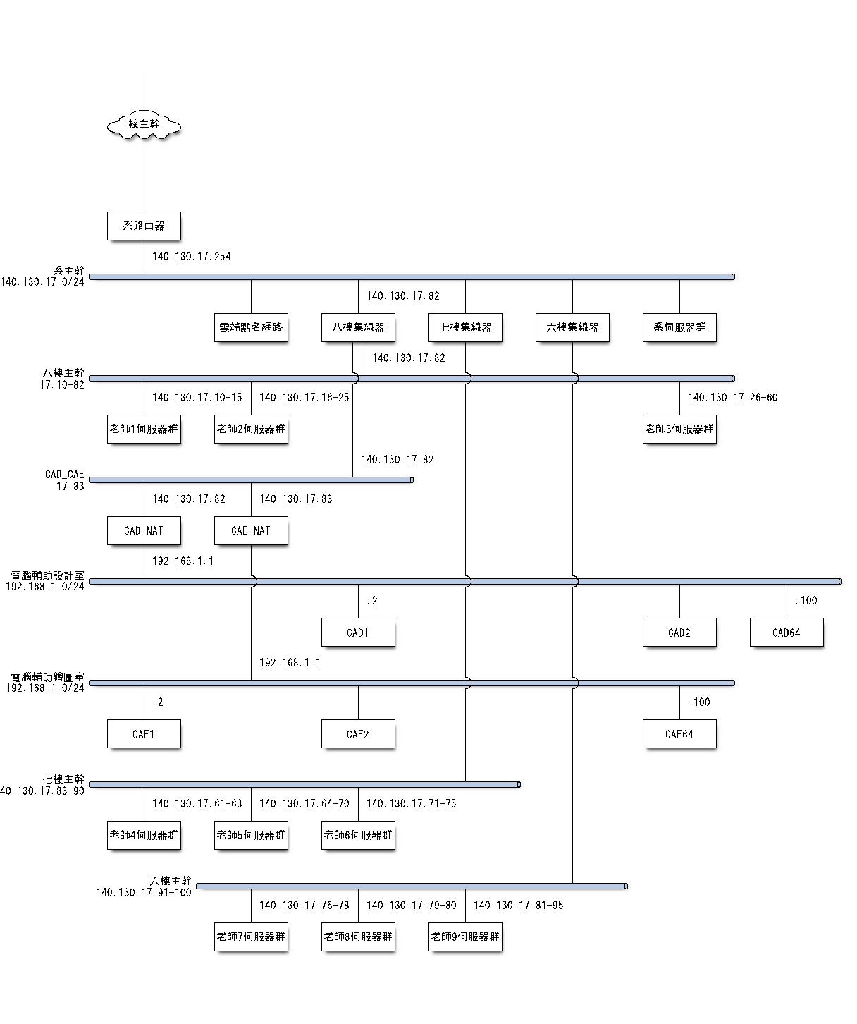
使用 Python3 與 http://blockdiag.com/en/中的 nwdiag 工具繪製機械設計工程系的網路配置圖.
1 2 | #安裝 blockdiag 模組 pip install blockdiag |
1 2 | #安裝 nwdiag 模組 pip install nwdiag |

到SciTE下貼上以下程式碼
1 2 3 4 5 6 7 8 9 10 11 12 13 14 15 16 17 18 19 20 21 22 23 24 25 26 27 28 29 30 31 32 33 34 35 36 37 38 39 40 41 42 43 44 45 46 47 48 49 50 51 52 53 54 55 56 57 58 59 60 61 62 | nwdiag { default_fontsize = 15; 校主幹 [shape = cloud]; 校主幹 -- 系路由器; network 系主幹{ address = "140.130.17.0/24"; 系路由器 [address="140.130.17.254"]; 雲端點名網路; 八樓集線器 [address="140.130.17.82"]; 七樓集線器; 六樓集線器; 系伺服器群; } network 八樓主幹{ address="17.10-82" 八樓集線器 [address="140.130.17.82"]; 老師1伺服器群 [address="140.130.17.10-15"]; 老師2伺服器群 [address="140.130.17.16-25"]; 老師3伺服器群 [address="140.130.17.26-60"]; } network CAD_CAE{ address="17.83"; 八樓集線器 [address="140.130.17.82"]; CAD_NAT [address="140.130.17.82"]; CAE_NAT [address="140.130.17.83"]; } network 電腦輔助設計室{ address="192.168.1.0/24"; CAD_NAT [address="192.168.1.1"]; CAD1 [address=".2"]; CAD2; CAD64 [address=".100"]; } network 電腦輔助繪圖室{ address="192.168.1.0/24"; CAE_NAT [address="192.168.1.1"]; CAE1 [address=".2"]; CAE2; CAE64 [address=".100"]; } network 七樓主幹{ address="140.130.17.83-90" 七樓集線器; 老師4伺服器群 [address="140.130.17.61-63"]; 老師5伺服器群 [address="140.130.17.64-70"]; 老師6伺服器群 [address="140.130.17.71-75"]; } network 六樓主幹{ address="140.130.17.91-100" 六樓集線器; 老師7伺服器群 [address="140.130.17.76-78"]; 老師8伺服器群 [address="140.130.17.79-80"]; 老師9伺服器群 [address="140.130.17.81-95"]; } } |
根據
1 2 3 4 | Execute nwdiag command: $ nwdiag simple.diag $ ls simple.png simple.png |
將上述程式碼儲存為 .diag檔後, 假設路徑在 y:\tmp 底下則輸入
1 | nwdiag y:\tmp\simple.diag |

在該路徑底下就會有 simple 圖檔(.png)可以使用

